Pore Pressure Prediction
However, Pore Pressure plays a role in all geomechanical applications as the effective stresses (defined as total stress – pore pressure) controls deformation and failure of the rock.
Pore pressure is a key parameter for Hydraulic Fracturing design
State of the practice methodologies, Normal compaction trend – Eaton’s, Unloading- Bowers methods, depending on the overpressure generation mechanisms – are available from OFG experience.
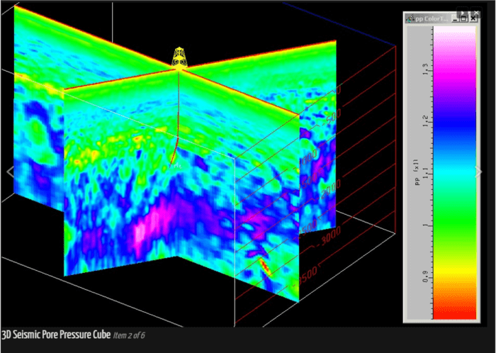
At reservoir scale PPP is done using seismic interval velocities with well derived relationships (Eaton, Bowers).
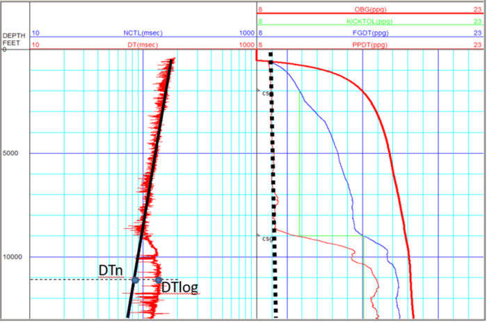
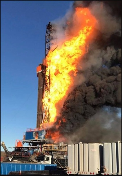
The main objective of PPP has been to prevent the risk and expense of kicks, blowouts, lost circulation and stuck pipe for drilling applications
How we handle PPP Unconventionals?
However, Pore pressure in Unconventional shales is a very challenging task because of the ultra-low permeability that impedes a fast response of gas/liquids inflows when drilling, even thought high overpressure may be present – no inflows detected. Also the high organic content alter the petrophysical response. So we use:•Corrected Eaton using poroelasticity, a very detailed Petrophysical model and thermal maturity •Empirical Equations based on TOC•Temperature vs effective stress relationships (thermal maturity)•Geomechanical back-analysis
Real-Time Pore Pressure Detection OFG assists in the PP RT analysis and detection by streaming real-time data and importing into the models, comparing to predrill estimates, and alert for corrections when needed. We can use several pore pressure detection methods such as D-exponent, LWD, field indicators – connection gas, total gas, mud gas, ROP, PWD, and wellbore failure indicators such as cavings morphology.
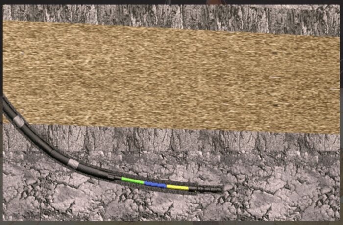
WELLBORE INSTABILITY during drilling
Starting with the geomechanical earth model (i.e. the distribution of stresses, pore pressure and mechanical properties) along a well trajectory and then using a geomechanical tool (analytical or numerical) to evaluate stresses induced by the borehole and comparing with a failure criteria are the steps to evaluate the critical conditions to design a safe well.
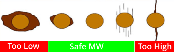
Which is the mud window, and optimum trajectory that will produce a stable well (avoid mud losses and fracturing the formation or prevent influx and excessive failure and stuck pipes).
Wellbore stability has been the main application of geomechanics in the oil and gas industry, to address problems of Stuck Pipe, Kicks, Lost Circulation, Sloughing Shale, inflows. Wellbore Instability, some 41% of total NPT – are estimated to cost the industry a combined $8 billion per year.
Critical Factors in wellbore Stability analysis
- Well Inclination and azimuth
- Permeable vs. Impermeable• Errors in Pore Pressure
- Errors in Stress – Influence of SHmax
- Errors in Rock Strength
• Influence of Failure Model
• Effect of Anisotropic Strength (bedding planes and natural fractures) - Thermal Effects
- Shales: Mud salinity and chemical effects
Design – Predrill safe mud window
As a function of depth

At any orientation and inclination (set depth)
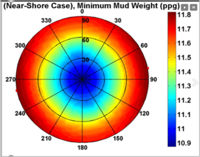
RT – Safe mud window
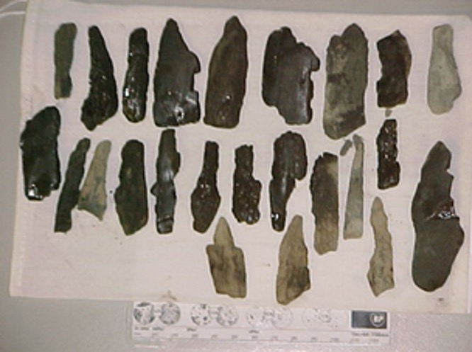
One step further in the RT PP prediction is the use of wellbore failure indicators to update the wellbore stability analysis in Real time. The future of cavings volume and morphology automatic recognition is coming soon.
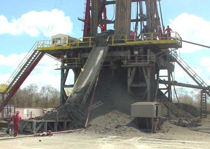
WELLBORE INSTABILITY during production (sanding)
Sand Production or ‘Sanding’ is the failure of the producing formation, followed by theflow offailed rock into the wellbore; very often the flow of failed rock can come to the surface and into surface facilities.
Rock failure modes include: A) shear (high stresses, low wellbore pressure, low rock strength); B) tensile (high flow rate, perm damage at the cavity surface); and C) erosion(high seepage forces).
What type of models and analysis we use:
- Phenomenological models (correlations, field observations)
- Analytical models (are they over- simplified? OVER CONSERVATIVE)
- Semi-empirical (getting better, need calibration)
- Numerical (coupled-uncoupled hydro-mech, allow for design and optimization)
- Integrated models
• Empirical, semi-empirical analysis
• Numerical analysis of TWC
• Numerical analysis of stability of perforations
• Field assessment of sand production potential and remedies


Flow Sanding
| Formation failure | Solids Flow | Solids Handling |
|---|---|---|
| Stress (Orientation & Magnitude) | Flow Rate | Downhole |
| Pore Pressure f(time) | Fluid Type f(viscosity) | Wellhead |
| Strength f(time) | Completion | Separation |
| Completion | Well Design f(size) f(trajectory) | Disposal |