The OFG Hydraulic Fracturing Workflow for Unconventionals is as follows:

Our workflow consists of five primary steps:
- – Characterization and evaluation of the reservoir formation with a particular emphasis on the evaluation of rock fabric;
- – Evaluation of the geomechanics model data as well as the geomechanics of the rock fabric, if present;
- – Reservoir flow modeling (performed by a 3rd party or the client);
- – Selection and utilization of the appropriate engineering tools and numerical simulators; and
- – Monitoring and feedback in order to optimize
OFG Services for Hydraulic Fracturing Optimization
> Reservoir Characterization Support
- As shown throughout our website, OFG can support our clients through:
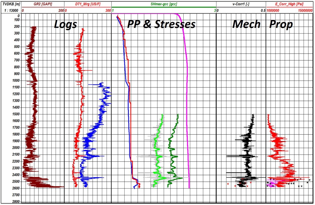
- – Geomechanical assessment (stress, pore pressure, and rock mechanical properties – 1D or 3D sector models) for the rock matrix as well as rock fabric.
- – Design, oversight and interpretation of a Data Acquisition Program – whether log-based, core-based or a proper combination.
> Geomechanical Evaluation of Microseismic Data
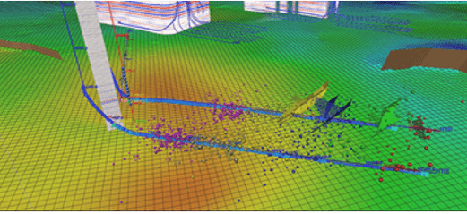
Microseismic data, for hydraulic fracturing monitoring, has been both a game-changing means of evaluating hydraulic fracturing propagation and growth and a serious source of misinformation and misinterpretation regarding the geomechanics of hydraulic fracturing and, most importantly, the evaluation of drainage volume from a given hydraulic fracture.
Field microseismic data is the acoustic representation of the energy released during rock shear failure. Tensile failure occurs, but is most often beyond the acquisition limit of the tools employed. Equally important, there is a threshold limit even for shear event acquisition – which means that field microseismic data represents only a subset of the actual rock failure events that occurred.
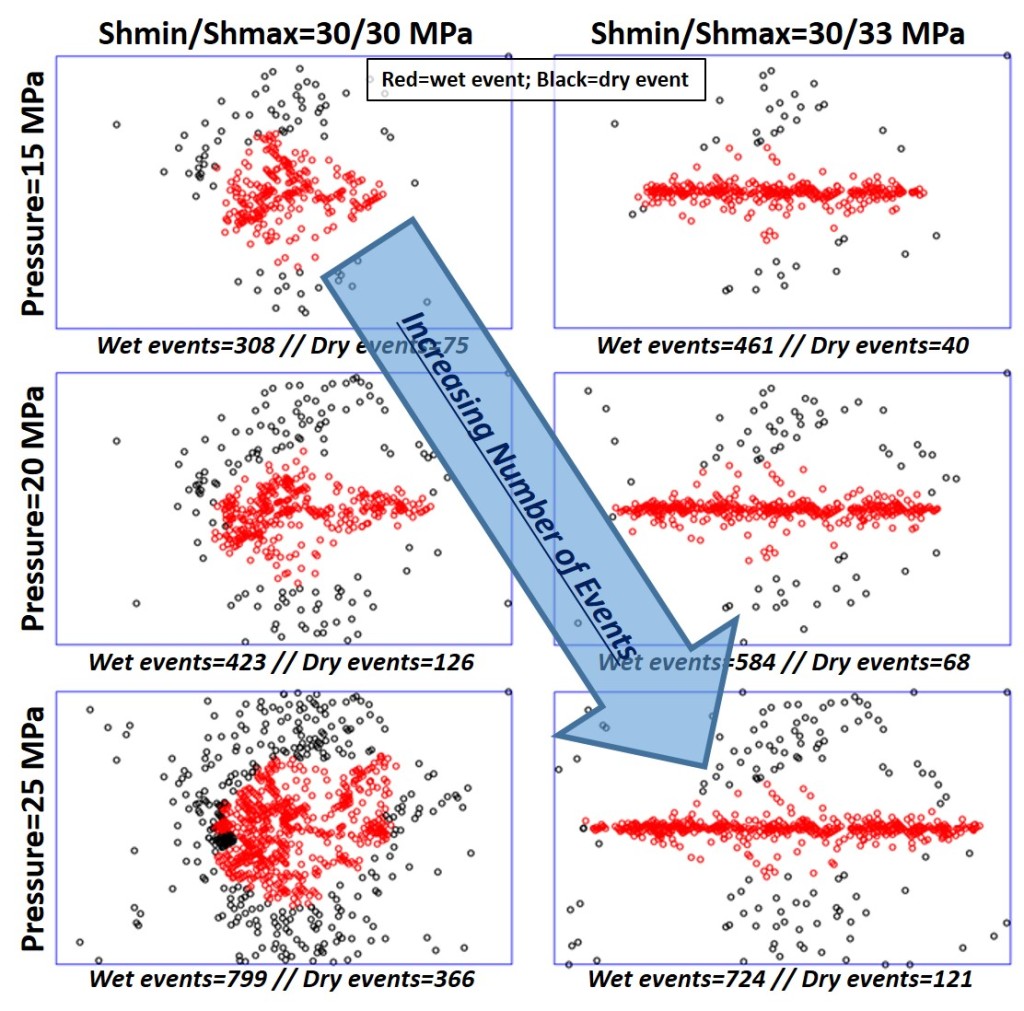
At OFG, we neither recommend nor utilize (when possible) the Stimulated Reservoir Volume (SRV) concept. We have long believed that SRV was a misinterpretation of the geomechanics of MS data and an incorrect evaluation of hydraulic fracture drainage volume. We have published several technical papers on the topic and, more importantly, current published SRV papers, reflecting heavy filtering of the MS data, support our position.
Utilizing basic geomechanics principles, coupled with the appropriate numerical simulators, we can support our clients’ interpretation of MS data as well as its proper use in hydraulic fracturing optimization.
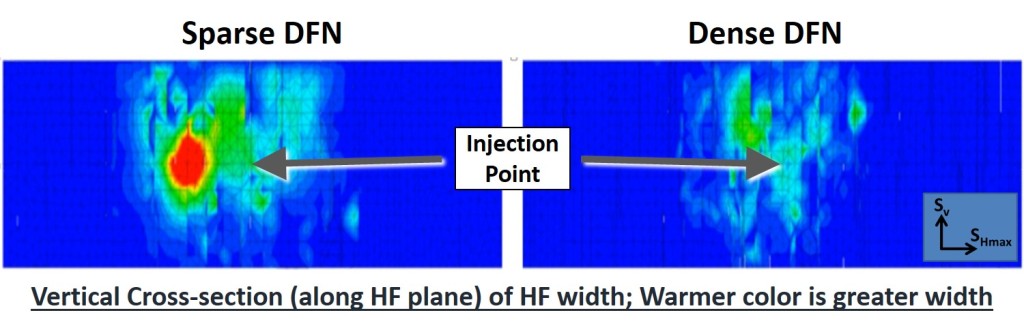
> Hydraulic Fracture Design and Optimization
OFG is not married to any particular hydraulic fracturing simulator or vendor. We are independent and utilize the right tool for a given project – whether that be a commercial simulator, a research simulator or analytical processes. Our services in support of hydraulic fracturing operations include:
- – DFIT/FET/Mini-frac design and interpretation;
- – Evaluation and optimization of operational parameters (rates, volumes, etc.);
- – Evaluation and optimization of stage spacing-stress shadows;
- – Post-frac analyses; and
- – Simulation history-matching to field MS data and injection data

> Stress Shadows and Multi-well Fracturing Optimization
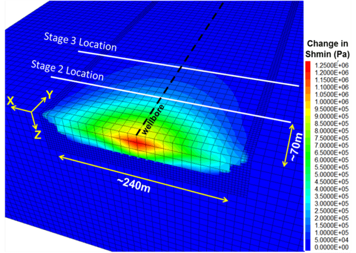
A fundamental principle of elasticity is that “stress causes deformations and deformations cause stress“. This simply means that, just as a change in the in-situ stresses will cause the rock to deform, so, too, will a deformation of the rock impart stress changes.
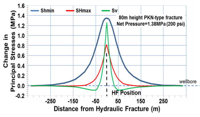
As the hydraulic fracture opens, it pushes on the formation – which leads to an increase in the minimum horizontal stress, Shmin. At the same time, due to Poisson’s ratio, the change in Shmin causes a change in the maximum horizontal stress, SHmax, and the vertical stress, Sv.
It is important to note key aspects of Stress Shadows:
- – Since the stress change is caused by the deformation, only where there is a deformation is there a stress change;
- – If the deformation changes (say, between the time the pumps shut-off and the fracture closes on proppant), the stresses change; and
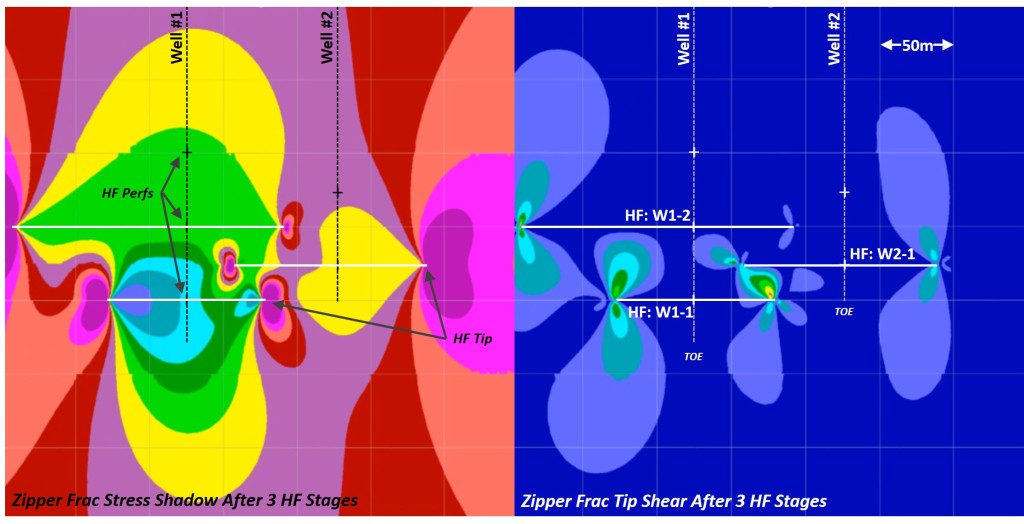
- – A hydraulic fracture propagates against the local stress field. If that stress field has been changed (due to Stress Shadows), then Stress Shadows will affect the propagation of subsequent hydraulic fractures.
OFG can support our clients by evaluating and designing:
- – Stage spacing/cluster spacing including Stress Shadow effects;
- – Multi-well stimulation strategies (Simul-Frac, Zipper-Frac, etc) accounting for Stress Shadow effects (both changes in the normal and shear stresses);
- – Well placement (landing location) and well spacing/ orientation; and
- – Multi-formation (stacked play), cube-type developments.
> Upscaling, Flow Simulation, Production Predictions & History Matching

OFG does not offer reservoir engineering services; rather, we work closely with 3rd parties (or directly with our clients) to support reservoir engineering efforts including:
- – Upscaling efforts;
- – Production history matching;
- – Flow model developments and inputs;
- – Production forecasting and economics.