Cap Rock Integrity
– injection pressure and volumes for gas storage in depleted reservoirs, water injection for pressure maintenance.
Changes of reservoir pressure induce changes in Shmin (Fracture Gradient) and therefore the safe injection pressure for cap rock integrity decreases. The injection pressures that are sustainable to perform waterflooding operations are no longer safe with pressure depletion inducing loss of cap rock integrity – we will be injecting fluid out of the reservoir.
The 3D geomechanical analysis coupled (one-way or two-way, or fully coupled) with reservoir modeling, can indicate the operational limits as reservoir pressure/stresses change.
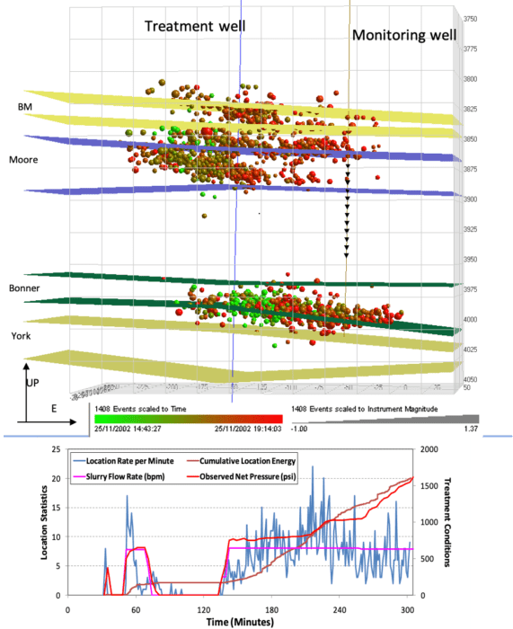
Fault Stability – Seismic Activity
– injection/depletion close to faults: hydrocarbon leakage, triggered/enhanced seismicity.

Fluid injection – increase in pore pressure – near faults in areas with high in-situ shear stress (most likely strike slip tectonic regimes) are prone to induce or trigger failure of weak planes (natural fractures or faults) and produce seismic events. Some of these earth quake are of low magnitude (microseismic) but if can be as high as M 4 or higher.Understanding the in-situ stress magnitude and orientation, pore pressure changes and fault geometry are critical to be able to predict the likelihood of the seismic events.
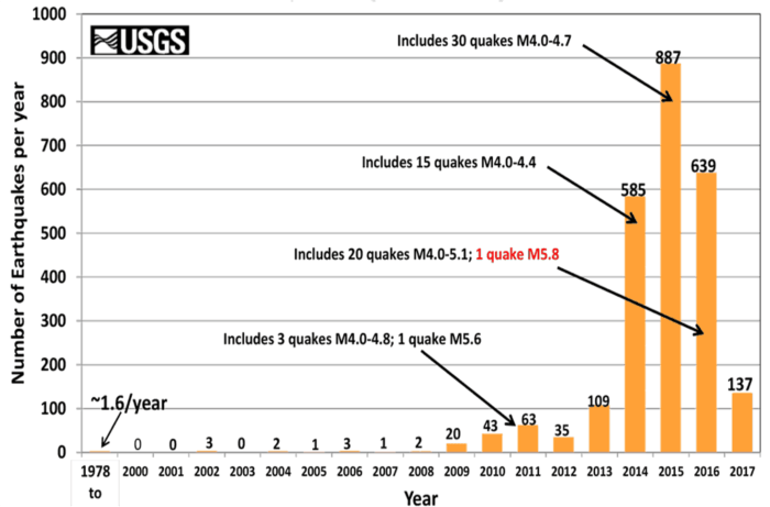
Induced Seismicity
Where the causative activity can account for most of the stress change or energy required to produce the seismicity
Triggered Seismicity
Where the causative activity accounts for only a fraction of the stress change or energy associated with the seismicity (i.e. tectonic loading plays a primary role)
(after McGarr & Simpson, 1997)
Cavern Stability
in salt mining
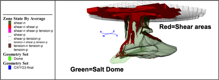

Geomechanical modeling including the salt dome showing shear areas. The location of a failed cavern close to the wall of the dome is shown. The cavern stability was also modelled at a fine scale.
Naturally Fractured Reservoirs
– geomechanical analysis – natural fractures may close with irreversible perm loss.
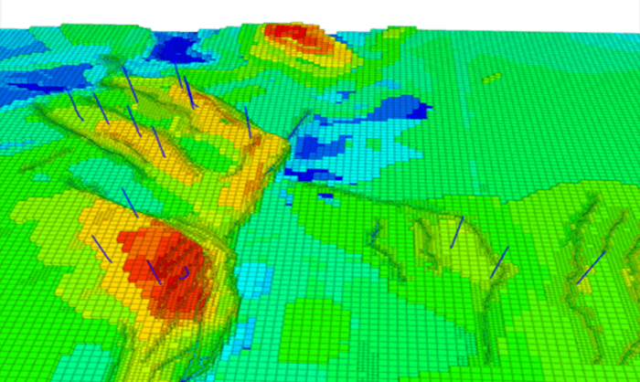
Three-Dimensional Geomechanical Model
Including faults and stratigraphic layers from surface to underburden, calibrated with well and core data.
Discrete Fracture Model At Field Scale/ Well Scale
Calibrated for intensity, geometry and hydraulic properties of fractures, and scaled to the dual porosity model.
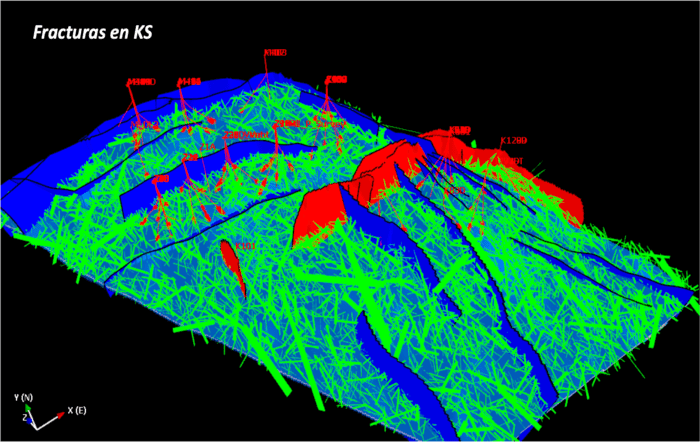
Stresses and pore pressure in the natural fractures geometry and location are determined to asses if those are in critical stress conditions and consequently, ready to slip. These are more likely to be hydraulically conductive. Also the deformation of the fractures can be modelled using laboratory obtained relationships (Barton/Bandis type models)
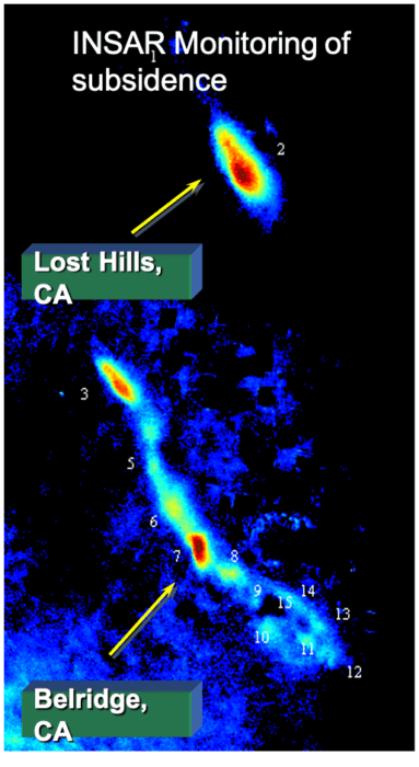
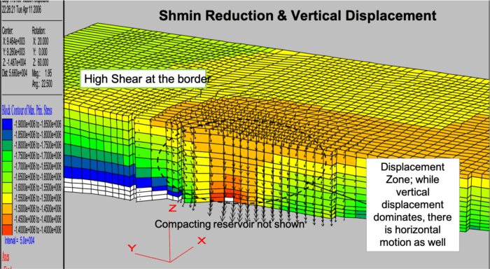
Compaction and Subsidence

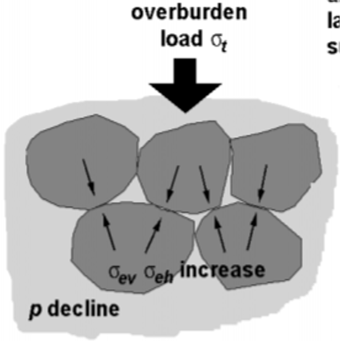
- Due to pressure decline the effective stresses increase and the rock deforms and compact.
- The perturbation can propagate to the surface (subsidence)
- Reservoir compaction and overburden stress/strain changes could lead to fault reactivation.
- Geomechanical simulators are used in combination with fluid flow simulations to determine reservoir compaction and surface subsidence.
- Models are calibrated/validated with measurements in the surface (Insar or bathimetry of the sea floor).