Casing deformations are not new to the oil & gas industry. Historically, casing deformation were associated with compacting and/or highly over-pressured reservoirs and, with pressure depletion, the stresses in and around the reservoir were altered leading to formation deformations and possibly casing deformation and failure. With Unconventionals, casing deformation has become a growing problem where casing deformations have restricted hydraulic fracturing operations in heel-side stages or restrictions in the build section may influence any frac stage.
The first step in a casing deformation analysis is to isolate the (common) location of the deformations and operations during which they may occur. Poor operation practices or inferior hardware have been shown to contribute to some casing deformation cases and need to be separated from a geomechanical evaluation of casing deformations.
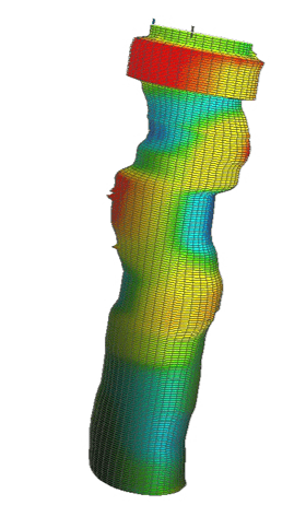
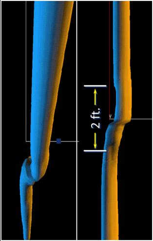
Once the location of the casing deformations is determined, along with the operational conditions during which the deformation occur, the morphology of the deformations needs to be evaluated – often with a high-resolution multi-arm caliper. This morphology, if analyzed properly, can separate buckling failure from shear deformations and may provide the orientation and direction of shear.
After the morphology of the deformations has been established, a 3D geomechanical model can be developed to simulate the conditions under which the deformation occur – leading to a predictive model of casing deformation in order to evaluate the efficacy of casing and stimulation design changes.
OFG has helped clients – in both conventional and Unconventional reservoirs – evaluate their casing deformation challenges, and we have performed geomechanical evaluations in order to predict and mitigate these challenges.
Frac Hits
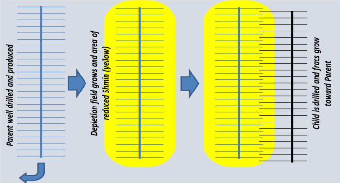
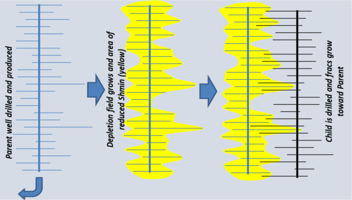
Frac Hits, which are sometimes called Fracture-Driven Interactions (FDIs), sometimes involve proppant but, at the core, most Frac Hits involve unexpected pressure communication between wells. When they occur, the common questions are: 1) “Why/when does it happen?” and 2) “How do we predict or prevent them?”. There are two primary scenarios to consider when addressing these questions:
- – Simply having too close a well spacing; or
- – Rogue-length hydraulic fractures.
The first scenario is really a reservoir management question involving a fundamental understanding of reservoir behavior (primarily permeability) and the typical drainage volume of the hydraulic fractures and wellbore. The geomechanics of the second scenario, rogue-length hydraulic fractures, comes down to determining and predicting those factors that cause rogue-length hydraulic fractures. These factors include:
- – cluster efficiency;
- – the stress regime and heterogeneities within the stress regime;
- – Stress Shadow effects; and
- – rock fabric.
At OFG, we have the experience, engineering know-how and tools to help our clients evaluate and prediction FDIs in their operations.